DISCLAIMER

All rights of photos and text reserved. Usage of photos or text from my blog on other websites or for any other purpose only with prior permission. If you want to use any material from my blog please contact me by email.

Thursday, February 28, 2013

Low Cost Single Ended 6CB5A Amplifier - Part 1

Hi!

In 2011 I already introduced a low cost version of the 6CB5A amplifier concept in the article single ended amplifier concept part 4. I occasionally get complaints that most of the designs which I present and offer as kit are too expensive. Therefore I would like to give this low cost amplifier design more attention. I recently finished mono blocks based on this circuit. I will outline the schematic and building process of these amps in detail in this and the upcoming articles.


Why mono blocks? You might wonder since most of my amps are stereo builds and I am a proponent of stereo amps rather than mono blocks. Two reasons: I had two small wooden chassis on hand which are just big enough for a mono block, but not a stereo amplifier. And secondly, mono blocks seem to be very fashionable, although there is no real advantage to a mono design over a well implemented stereo amplifier. So I follow the taste of the crowd on this one, although it doesn't make a lot of sense, especially for a low cost object.

In order to keep cost as low as possible, certain compromises are necessary. An obvious one is the interstage transformer which has to go. A RC coupled driver stage will do the job. Also no expensive oil caps. Electrolytics will fit into the restricted space and are the lowest cost option. This probably is the biggest compromise. Also the PSU needs to be a bit simpler, no external PSU.


The schematic shows the whole circuit including power supply. Unmarked resistors can be 0.5W types. Approximate voltages are given for the most critical nodes. Let's go through the schematic step by step, starting at the input. The resistor to ground after the input defines the input impedance of the amp which will be 100kOhms in this case. It also serves as grid to ground resistor for the 6N7 input tube, to ensure the grid is at ground potential. The 6N7 contains two triodes with a common cathode. The grids and plates of the two sections are tied together. The input tube is cathode biased with a 1k resistor to ground. This will set the bias approximately at -4.5V and will result in 4.5mA current through the tube. The cathode resistor is bypassed with a 100uF electrolytic. Gain of the amp is on the low side, so we need to get all the gain from the 6N7 we can, therefore we need that bypass cap. The tube has a 47k plate load resistor. At minimum a 10W type should be used. I use 20W Dale aluminium resistors there. The plate of the 6N7 will settle at about half the B+ voltage.

The driver is coupled through a 100nF capacitor to the output tube grid. I  used a 1000V MKP foil there. At minimum a 450V should be used. The output stage is also cathode biased with a 1k resistor. Since we do not use the ultrapath approach as in my usual designs, this needs to be bypassed with a 100uF cap. The cathode resistor dissipates quite some power, so a 20W type is recommended. Again an aluminum Dale resistor does it for me. The 6CB5A needs a grid to ground resistor of max 500k for save operation. Since I didn't have 500k at hand, I wired two 1M resistors in parallel. The screen grid is connected to the plate through a 100 Ohm resistor which should be placed close to the screen grid pin.

The 6CB5A works well with plate loads of 3.5k upwards. I prefer amps with a decent damping factor to make them usable with a wider range of speakers so I recommend 5k. Lundahl has some quite reasonably priced output transformers which fit the bill. LL1663/70mA would work well. For this particular build I chose the LL1682/70mA for an even lower output impedance. It is a 5.5k:5 transformer. This way the amp can be used with either 4 or 8 Ohm speakers.

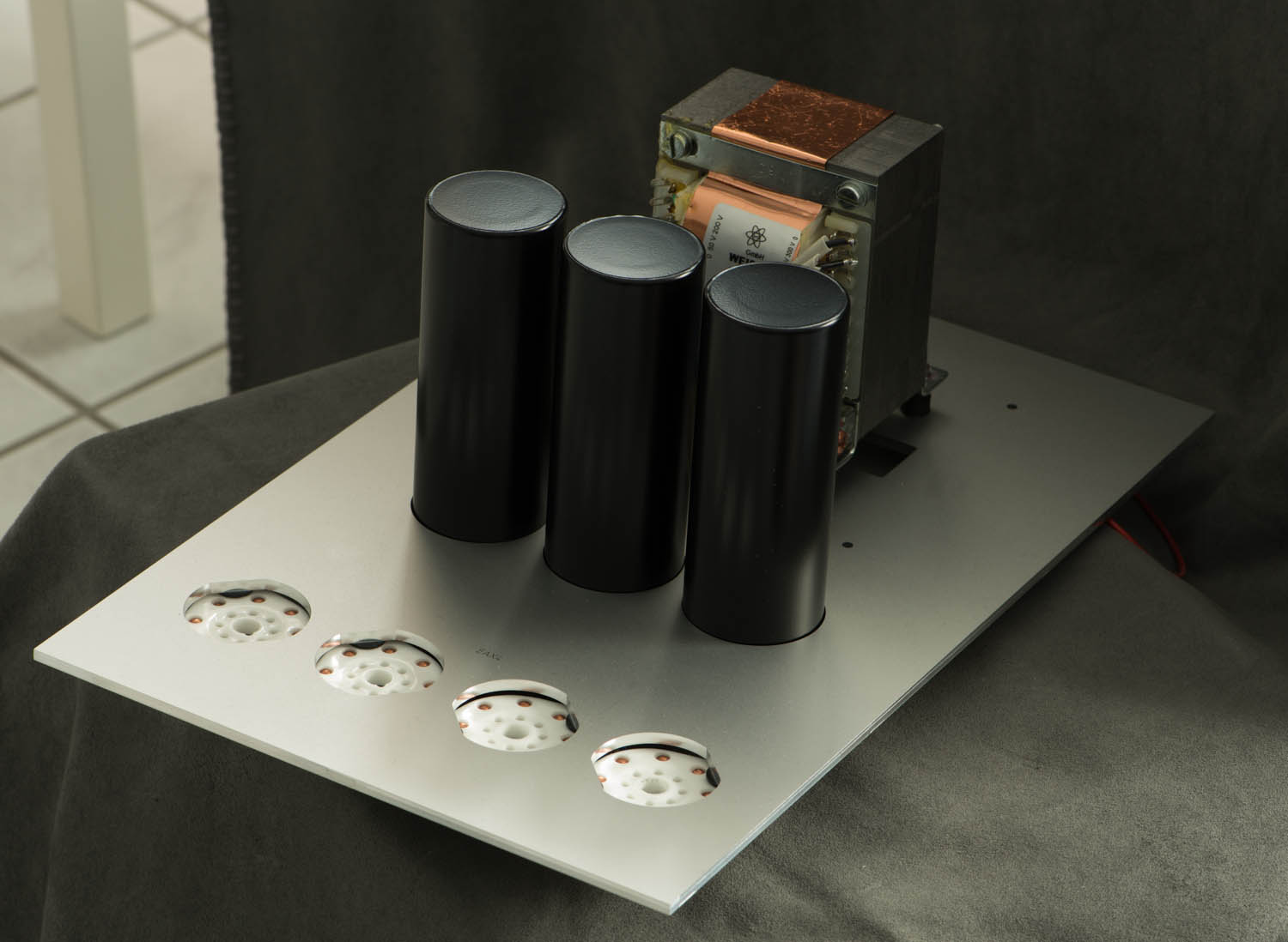
Let's have a look at the power supply section. I gave up my favorite choke input supply concept since this usually needs at least two chokes to get the ripple down. I didn't want to give up chokes all together, so a single choke stayed in there. A Lundahl LL1673 20Hy/100mA choke or anything similar will fit the bill. No compromises in the power transformer for me. So I picked a medium sized type from my power transformer range. It has a secondary which can be configured from 100 to 600V in 50V steps at 200mA. There are two 6.3V/5A heater windings. One of the heater windings is used for the 6N7 and 6CB5A. This winding is referenced to ground through the two 100 Ohm/5W resistors. Since there is another heater winding, a Tube rectifier can be used. I chose the 6BY5 which will be augmented by two UF4007 silicon diodes. This creates a hybrid rectifier bridge which maintains most of the advantages of the tube rectifier. The secondary is configured for 350V. This yields about 425V DC after the CLC filter. Since there is considerable ripple across the first  capacitor after the rectifier, two 22uF/450V electrolytics are wired in series. Two 100k/5W resistors in parallel to these ensure that the voltage divides equally between the two capacitors. At the same time they act as bleeder resistors. A big capacitance is needed after the choke since it supplies both the driver and output stage and it needs to reduce the ripple to an acceptable level. A minimum of 100uF/450V is needed. More will not hurt I would recommend 100-200uF.

This circuit can be adapted for stereo with a single common supply. The supply sections needs to be doubled in current capacity and I would recommend a minimum of 200uF B+ smoothing capacitance after the choke. Although a bigger power transformer would be about 50% more expensive, only one of them is needed in a stereo amplifier and only one choke. On top of that only a single chassis. The smart cheap skate would go for a stereo amp.


Stay tuned for the next parts of this series which will outline the construction in detail.

Best regards

Thomas

Wednesday, February 27, 2013

Music: Ella Fitzgerald - Songs from Let No Man Write My Epitaph

Hi!

If you have read some of my older posts about music, it will be no surprise that I like Ella Fitzgerald. She did many records and pretty much all of them are very good. This one is my favourite: Ella Fitzgerald sings songs from the soundtrack of Let No Man Write My Epitaph.


This album was recorded in April 1960 and released under the Verve label. This is a great collection of songs. She is accompanied by a piano, played by Paul Smith. Pretty much all of the songs are slow ballads. This album was recorded in a similar quality as other Verve albums of that period. The voice is extremely colourful with lots of timbre. Especially the vibrato in Ella's voice is beautifully preserved. The high end of the frequency spectrum lacks a bit, but that is quickly forgotten when you are lost in that beautiful voice.


The best song on the album: 'Black Coffee' The first song on side one.


If you are looking for lot's of tone and colour like me, get this album on vinyl and savor it!

Best regards

Thomas


Wednesday, February 20, 2013

Making of a D3a LCR RIAA Phono Preamp - Part 2

Hi!

The initial construction steps of the D3a LCR phonostage have already been shown in part 1. In the meantime the wooden frames for the chassis arrived and the phono stage got completed.


The different sub modules get assembled into a stack which mounts behind the front plate:


Starting from the left, two B+ decoupling chokes and the transformers of the first stage which drive the LCR RIAA which is mounted on two tiers in the middle followed by the transformers of the second stage.

The inside of the power supply unit:


The preamp section completely assembled and wired up, before the bottom lid is attached:


The power supply:


Finished preamp section:


The power supply unit:


Some people prefer red LEDs as power on indicator.

Phonostage and PSU together:


The back sides showing the input and output connectors:


How does it sound? I am very pleased with the result. The phono stage has a very detailed and transparent presentation with especially accurate voice articulation as I am used to from LCR phono stages. This implementation has a very solid and colourful bass which reaches very low. Measurements also confirm the good bass response with the -3dB point at about 10Hz which is excellent for a transformer coupled design like this. The top end is also reaching quite high with the -3dB point around 40kHz.


As expected gain is quite high. It measures a bit above 40dB (this preamp is MM sensitivity, meant to be used with an external MC step up). While this does not seem extremely high, it is combined with an output impedance of less than 200 Ohms. Which means the phonostage can drive either a transformer volume control directly with ease. Or, if more gain is needed it can feed a linestage with an input transformer, which can yield 12dB additional gain if a 1:4 step up is used. Alternatively the output transformer of the phono stage could be rewired for close to 1:1 ratio which would also yield about 12dB more gain at a still reasonable output impedance of about 2 kOhms.


The D3a proves in this phono stage that it is a worthy alternative to the very rare EC8020 which remains my favourite small signal tube. After completing this phono stage and listening to it, I increased my stock of D3a tubes.


Stay tuned for updates of the matching linestage and 45 mono blocks as they get finished

Best regards

Thomas


Friday, February 15, 2013

SE 45 Amp With 45 or 10Y Driver - Part 1

Hi!

In this article I will show the initial construction steps of single ended 45 mono amplifiers which I was requested to build. The amplifiers will have a directly heated driver stage which can be configured to use either another 45 or a 10Y.


These monos are meant to be used with the D3a phono stage which I introduced in the previous article. They will share the same chassis concept. This is the top plate which carries the tubes, capacitors and transformers (Tango XE20A output and NC20F interstage):


The tube on the left is the driver tube which can be configured for either 45 or 10Y by the switch behind it. The switch changes the cathode resistance and adds a dropping resistor into the filament feed to adjust the voltage.


The switch behind the output tube on the right is a ground lift switch. 


The signal wiring and grounding arrangement:


The remaining parts are mounted on sub modules which will be placed inside the chassis:


The one on the left carries the input transformer which is needed to bring the input sensitivity of the amplifier to a sensible level. This is necessary since the driver tubes have very low gain. The amps will be used with a 10Y line stage which has sufficiently low output impedance to drive these transformers. Both tubes are heated by DC, passively filtered by separate LCL chains. Both stages will have their own decoupling chokes for B+.

The front and back plate:


The power supply shares the same style as the PSU of the D3a LCR phono:


Separate heater transformers for each tube, the first coils of the filament LCL chain and the B+ smoothing chokes will be placed inside:


The front and back plates of the PSU:


Stay tuned for an update as these amps get finished

Best regards

Thomas

Friday, February 8, 2013

Making of a D3a LCR RIAA Phono Preamp - Part 1

Hi!

I have been working on a complete amplification  chain containing phono stage, line stage and mono amps during most of the last month. They will all share the same chassis style as my 10Y line stage. Each with external PSU, so 8 chassis total. I will show all of them in dedicated posts. This first post shows the current state of the D3a phono stage.


I already announced this phono stage in the D3a Tube of the Month article. The circuit topology is described there. The reason for the choice of the D3a is the higher amplification this tube can yield in an LCR phono stage compared to an E55L for example. The person who will use these electronics has a very low output cartridge. So every bit of gain is needed.

As already shown in previous posts about preamps, each socket is mounted on a small sub plate which is vibration damped through rubber pieces. Here a top view of the main mounting plate which will later be exposed on the top of the chassis:


The underside of the plate showing the signal and heater wiring:


Two of the 4 B+ decoupling chokes used in the circuit are hidden under the two black covers in the middle. The remaining chokes and transformers will be placed inside the chassis:


Both stages of the circuit use Lundahl LL1692A transformers. The 600 Ohm LCR RIAA is built discretely, using intactaudio RIAA coils:


The reason for the use of discrete LCR networks was the wish for the inclusion of the Neumann time constant. The second half of the network got modified such that the attenuation of the high frequencies stops around 50kHz.

Another requirement was the use of XLR in and outputs wired in parallel with RCA connectors:


The backside also carries separate binding posts for signal ground and chassis, the power supply connector and a ground lift switch. The back plate is prewired as far as possible before it is mounted to the preamp:


The PSU is constructed in a similar style, the top plate:


The power transformer will late be hidden under a black cover. The wiring underneath:


The separate power transformer for the heater supply and the B+ smoothing chokes will be placed inside the chassis on sub modules:


The front and backside panels of the PSU:


Now only the wooden chassis are missing. As soon as these arrive, the phono stage will be completed. This will be covered in part 2. 


Best regards

Thomas

Friday, February 1, 2013

Tube of the Month: The 6A6

Hi!

One of my favorite indirectly heated drivers for small output tubes is the 6N7 which was already presented as tube of the month almost 2 years ago. There is an electrically equivalent tube which is a predecessor of the 6N7. I have used it in the past as drivers in 45 amps. It's time that it get's it's own place in the Tube of the Month series. Here is the 6A6.


With it's gain factor of 35 it is just right for a 2 stage amp with useful input sensitivity. Plate resistance is low enough to drive small triodes like the 45 with ample head room.
It is actually a double triode with a common cathode. It was designed for Class B push pull output stages. With grids and plates wired in parallel it is great as Class A driver. It has a 6.3V heater which consumes 0.8A. Some might be scared away by the fact that it is a double triode. There is a misbelief that paralleling triode halves creates some smear or other loss of resolution. Not really a concern with this tube in my experience. Please see the 6A6 datasheet for all electrical parameters. The pinout of the 6A6 can be seen on the left. It has a medium 7-pin base which is also referred to as UX7. Two of the pins have a slightly larger diameter. These are the heater pins. Since there is no key in the center of the base as with octal tubes, the heater pins can be used to make sure the tube is inserted into the socket with correct orientation. The photo below shows the base with indication of the individual pins.


Although this is a less common base, availability of sockets is good. They are still produced. Below a photo of a chinese made ceramic UX7 socket.


As always we are mainly concerned about the linearity of the tube. Let's see what the datasheet curves tell us:


Let's see how this looks on a curve tracer with a different scale:


Looks like anything a tube audio designer can wish for!

A tube which is quite overlooked. NOS availability is good and prices are low. While the prices for 6N7, especially those in ST glass rise, the 6A6 stays in the tube dealers warehouses widely ignored. As far as I'm aware the 6A6 was only made in ST shape. No straight sided glass or steel bottles. Also no globes as far as I'm aware. It seems that the 6A6 was only manufactured over a rather limited time frame until it got replaced by the 6N7. The size of the bottle is actually quite large for such a tube. It has the same dimensions as a ST shaped 45 triode. Apparently the 6A6 was produced by pretty much every major vacuum tube manufacturer. All of the big ones: RCA, GE, Westinghouse, Sylvania, National Union. There are also some lesser known brands: Cosley, Delco, Arcturus, and the usual rebranders offered it as well. Below just a small selection of 6A6 tube boxes.


Some tubes of various brands:


A beautiful Ken-Rad 6A6 with blackened glass which was often done by this manufacturer:


The top of the Ken-Rad tube:


A Westinghouse:


This is a 6A6 from my collection which came in a generic white box. No brand marking visible on the tube. It has a dark brown base:


The top construction is a bit different from others. It only has a tiny mica strip for alignment of the electrodes and large springs which hold the entire structure:


Now let's have a closer look at the internals by dissecting a tube. We will examine this General Electric 6A6:


First the glass has to go off:


Now we can see the internals much better. Here a close up of the topside which shows the grid cooling fins:


If the tube is used in Class B push pull operation which can push the grids into the positive region there is some grid dissipation. These fins help to cool the grids a bit. Let's take the upper mica disc off so we can actually see the grid and cathode structure inside the plates:


One of the plates removed:


A closer look at the heater as it enters the cathode sleeve:


A close up of the grid structure with a scale in the background. The black vertical lines are 1mm apart:


The cathode and grid:


Heater removed from the cathode:


Maybe not as impressive as the D3a which I showed last month, or the EC8020, but still a marvelous piece of vacum tube engineering.

Finally some photos of a 6A6 lit up:


A close up of the heater:


The top side:


A close up of the cathode, through the hole in the mica, the grid is visible:


I hope you enjoyed the second Tube of the Month presentation of 2013. Stay tuned for more articles on interesting tubes during the coming months.

Best regards

Thomas